Read these notes first and then for further general information check the WIKI.
Amongst other things, it will tell you which keys on your camera correspond to <ALT>.
(for the 'A' series cameras it is the [Direct print] button).
First, you need to determine the firmware version of your camera and then download the appropriate ZIP file.
This is made very easy by Dave Mitchell's 'ACID' programme.
Ensure that you also download Common_files.zip.
All files should be unpacked into the same folder.
An installer (Windows only) is provided with the download that allows you to create single or dual-partitioned auto-bootable cards automatically setup for the left or right camera.
If you do not use Windows, Dave Mitchell has provided an installer for Mac OSX (10.3 or later) that should make the 'task' far easier.
The installer also allows you to copy or move image files to a selected destination folder.
Cards larger than 4GB are only recommended if you intend to shoot many movies as the dual-partitions required are not as convenient to work with.
Some cameras do not have dual-partition support and SDM does not support the manual firmware-update method that would allow use of large unpartitioned SDHC cards.
Card-readers built into laptops may not support SDHC cards, in which case an inexpensive USB SDHC card-reader will be required.
You have to swap partitions to access the images or movies and then remember to switch back again so that the card will autoboot.
Configuration Files
All SDM settings are saved in configuration (CHDK.CFG) files.The installer automatically uses a default configuration for the left and right cameras and assumes they are side-by-side and not inverted.
If one camera is inverted, simply choose orientation 'I' in the stereo menu after installation.
It is also assumed that the Canon OSD's are hidden (by cycling through the Canon options using the DISPLAY button).
If you want an alternative layout to avoid overlapping with Canon's OSD, Werner Bloos has provided configurations (in English and German) in the folder 'CONFIGS'.
It includes an option for an inverted left camera.
The readme file in that folder gives instructions for a new or existing install and provides support for cameras that have a non-standard colour palette.
NOTE:The G11, IXUS95,IXUS100, IXUS105,IXUS980, S90, S95, SX120IS and SX200IS do not use the standard CFG file, they use a file with a numeric value after 'CFG'.
These must be copied to the card manually and should not be renamed. Use the files supplied in the CONFIGS folder.
You can easily edit the CFG files in a user-friendly way using the CFG editor supplied with the download.
New SDM Install on cards 4GB or less
This is the easiest install and is mandatory for those cameras that do not support SDHC cards.
Download the zip for your firmware and also Common_Files.zip.
Unzip both to the same folder and check the following files and folders are present :-
- CHDK folder
- DCIM folder
- DIGI_SCRIPT
- DISKBOOT.BIN
- CHDK.CFG.L
- CHDK.CFG.R
- CONFIGS
- process.bat
- swap_bytes.exe
- CFGSSDMEDIT.jar
- SDM Basic Shooting guide
- sdminste.exe
Ensure that there is no other removable media plugged into a USB port (otherwise WinXP SP3 gives warning message regarding 'Vista').
Insert the unlocked card into the card-reader and Close the window that pops-up.
Double-click 'sdminst.exe'.
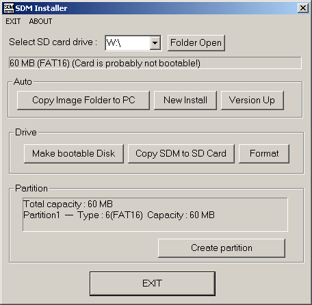
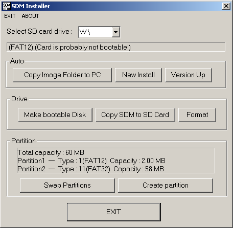
Select the SD card drive letter and click 'New Install'.
If the card is locked you will be prompted to unlock it and try again.
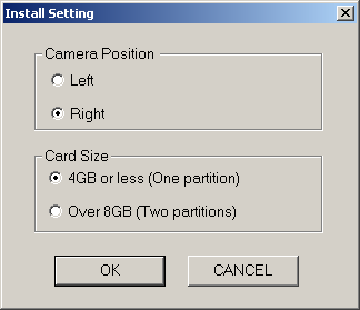
Choose camera position as 'Left' or 'Right' and ensure card size is '4GB or less'.
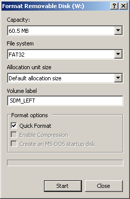
This will ensure that a single partition formatted FAT16 will be created if it does not already exist.
If the card is not already formatted, you may do so at this stage.
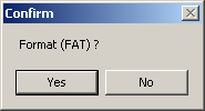
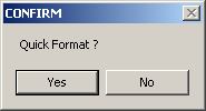
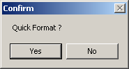
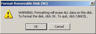
You will be asked to confirm formatting (as existing data will be deleted and auto-booting ability removed) and then asked if 'Quick Format' is acceptable.
'Quick Format' is fast because it does not test the card for bad sectors.
In particular, it may be preferred with Windows Vista which can otherwise be slow.
During formatting, you will be given the option to enter a volume label (SDM_LEFT or similar is suggested).
All required files will be copied to the card together with a configuration file (CHDK.CFG in the CHDK folder) that is setup for left or right camera.
Any existing files will be over-written.
The configuration file determines what the various options in the menus are set to.
You then simply lock the card, insert into camera and power-up in Record mode.
Some cameras power-up in Playback mode and you need to press the shutter to switch to Record mode.
For future power-ups, you can set the 'extend lens' option in the Stereo menu so that SDM automatically 'presses' the button.
New SDM Install on cards 8GB or more
The following cameras have support for dual-partitions that enables SDHC cards larger than 4GB to be used :
- A450
- A460
- A470
- A480
- A550
- A560
- A570
- A630
- A640
- A710
- G7
- G9
- G11
- IXUS70/SD1000 (not 100c)
- IXUS75/SD750
- IXUS90/SD790
- IXUS95/SD1200
- IXUS100/SD780
- IXUS105/SD1300
- IXUS850/SD800
- IXUS870/SD880
- IXUS950/SD850
- IXUS970/SD890
- IXUS980/SD990
- S5IS
- S90
- S95
- SX1IS
- SX10IS
- SX100IS
- SX110IS
- SX120IS LI>SX200IS
- TX1
Insert the card into the card-reader and then double-click 'sdminst.exe'.
If you start 'sdminst.exe' without a card in the reader, the dialogue-box will close
Select the SD card drive letter and click 'New Install'.
If no drive letter is displayed DO NOT proceed !
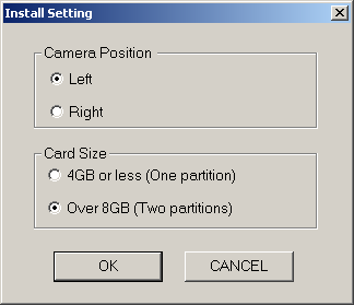
Choose camera position as 'Left' or 'Right' and ensure card size is '8GB or more'.
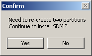
If the card has not been previously partitioned, a slightly tedious, one-off procedure needs to be followed to do this.
Click 'Yes' to continue to install SDM.
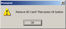
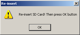
You will be asked to remove and re-insert the card at various stages and to then click the 'OK' button.
The partitions will be formatted and you can name them ('SDM_LEFT' and 'SDM_IMAGES' for example).
DISKBOOT.BIN will be copied to the first partition and the CHDK and DCIM folders will be copied to the second partition.
The images and movies will be saved to the larger partition.
Make sure that the 2MB partition is the first one (by swapping if necessary), lock the card, insert into camera and power-up in Record mode.
Problems with swapping partitions has sometimes been caused by 'faulty' card readers, that seem to vary in quality.
Creating Partitions
You can create a single partition on a card 4GB or less and two partitions on SDHC cards 8GB and larger.
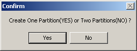
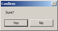
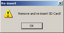
Choose one partition or two partitions, confirm your choice, click 'OK' and remove and reinsert the card when directed.
(Close the blank window that pops-up).
On completion, the dialogue-box will be updated with your partition details.
The partitions then need to be formatted.
Formatting Cards
You may format a card or the first partition of a dual partition card.
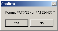
Choose 'Yes' for FAT16 on a single-partition card and 'No' for FAT32 for the second partition of a dual-partition card.
On dual-partition cards you can temporarily swap partitions so that the larger one may be formatted FAT32.
You may choose a 'Quick Format' option and will then be asked a final confirmation before formatting deletes existing data and removes auto-booting facility.
Copying SDM to the card
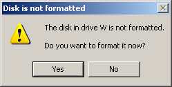
If the card is not already formatted you will be given the option to do so.
Choose FAT16 for a single partition or the first partition of a two-partition card.
Choose FAT32 for the second partition of a two partition card.
In the latter case, you will need to temporarily swap partitions so that the larger partition becomes the first partition.
Enter a suitable volume label and normal format or quick format.
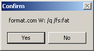
After you confirm that formatting is required, the partition will be formatted.
All SDM files and folders will be copied to the card.
For dual partitions, DISKBOOT.BIN will be copied to the first partition and the DCIM and CHDK folders to the second partition.
Updating an existing SDM installation
An existing installation will already be partitioned, formatted, made bootable and contain all required files and configuration settings (in CHDK.CFG).
After confirming if the card has one or two partitions, the new DISKBOOT.BIN will be copied to the card together with any new or updated utility files (scripts, grids, fonts, etc.).
A new configuration file will be installed and your existing one renamed CHDK.CFG.OLD.
Sometimes you can use your old configuration file, it depends what changes have been made to the software.
Copying and moving images to the PC
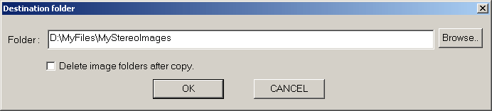
Select the destination folder and all images will be copied there.
You have the option of deleting the image folder on the camera.
On completion, the destination folder will be opened for exploring.
Preparing your switch unit and checking the batteries
.
Use of this USB-triggering method is entirely at your own risk.
No responsibility can be taken for any consequences resulting from it's use.
You can make your own switch unit or you can buy commercial units that may be used modified or unmodified.
A DIY switch-unit is simply required to switch a voltage across pins 1 and 5 of the camera's mini USB connector.
With the connector's wider part at the bottom and looking into it, the +ve connection is on the left.
On older cameras, a 3V battery is sufficient and a button-cell can be used or two AA batteries.
If that does not work on newer cameras, you could try two Energizer Ultimate Lithium batteries that have an open-circuit voltage of 1.6 to 1.7V
Beyond that, three 1.2V or 1.5V batteries may be used.
It is not advised that voltages higher than 5V be used although there is no evidence of 6V causing damage.
The current-load is very small so diodes may have a smaller voltage-drop than the nominal 0.6V and you may wish to connect two in series.
Some users have adapted very inexpensive torches that have the switch and battery components.
The above diagram shows the connections for a Type 'A' USB(1.1 or 2.0) connector (the computer end of the camera's USB cable).
Zosim's webpage shows further details of a switch unit using Type 'A' connectors.
Any DIY switch unit would probably cut-off the large Type 'A' connector and hard-wire the cable directly to the switch unit.
Far more suitable than cables intended for computers are those intended for charging mobile phones.
They are far more flexible and have right-angle mini USB connectors.
See Damir's Links for USB right-angle connectors, cables and adapters. and Grant Campos' 3D Sales
Be aware, that some of the plugs contain additional components that may or may not affect operation.
If you want a ready-made switch unit, they are available here from Germany.
At present, nothing seems to be available from other countries.
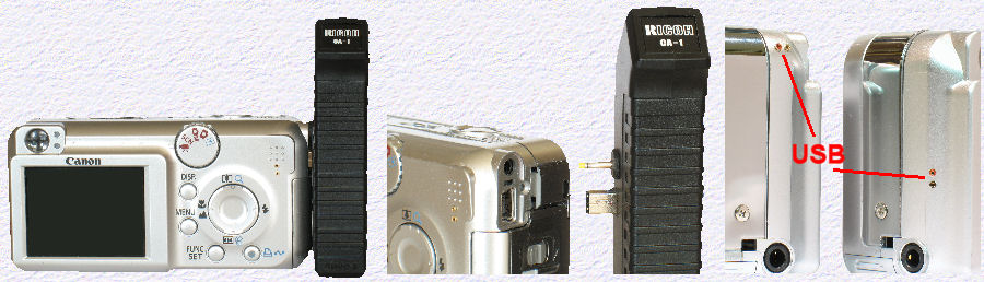
SDM 1.60 and later supports the Ricoh CA-1 switch unit.
This device works off a single 1.5V battery yet generates 5V pulses that will suit all camera models.
It has the advantage of operating like a normal camera remote (see below).
If you can adopt a DIY approach, you will need to connect a second USB cable inside the switch unit.
There is sufficient room and you should tie a knot in the cable-pair to provide strain-relief.
Be careful that you do not solder for too long or the PCB pads may lift.
With the switch held upright, the +ve connection for the USB cable is the solder-pad on the right (with a trace leading to a 1K SM resistor).
The ground connection is on the left.
Be careful that you do not break the head on the on/off switch.
If you do, it is a Copal Electronics CUS-12B available from RS Components in many countries.
(Andrew Woods on the Yahoo SDM Group may be able to provide one.)
If you are experienced at 'hacking' cameras, the above shows a very compact solution.
Tiny sockets are provided so that a two-conductor ribbon cable joins the cameras USB connectors.
If you do not wish to open-up the switch unit (you have to be careful when re-assembling it), you could cut the supplied cable and splice-in a second,flexible cable and connector.
Uwe Glaessner has constructed a hard-wired ixus 55 twin-rig that does not use a USB switch.
Instead, the software has been modified to use shutter half-press instead.
Details on his blog Homemade 3D Digital Stereo Equipment
Remove the USB leads when transporting or shipping your cameras to avoid damaging the circuit board connections