Serial Communication with an external device
SDM includes the 'send_data' command that allows a script to send three bytes of data to an external device by flashing the Print LED for varying amounts of time.
The shortest pulse is known as the 'unit pulse' and its value is set in menu Advanced\Serial Comms in increments of ten milliseconds.
A commercial device known as clickPAN SDM is available that uses the send_data command to control servos on a motorised rig for kite aerial photography.
Examples of scripting with the 'send_data' command may be found here.
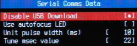
You may apply a tuning factor in order to set the pulse-width more accurately.
The pulse-width will vary (typically over a range of 1.3 msec on the A620), presumably due to interrupts from the Canon firmware, so you should choose a value that will give reliable results with your external device.
A 10 or 20 msec unit pulse is suggested as a minimum.
The protocol is very simple, the pulse widths as multiples of the unit-pulse are :-
Start bit 4
Logic 0 1
Logic 1 2
Interbit space 1
Interbyte space 3
After the start bit, three bytes are transmitted.
After the interbyte space of three unit pulses, the start bit and three bytes are sent again.
The receiving device should compare the two sets of data and if they match drive USB V+ high within 100 msec of trailing interbyte space ending.
After a suitable delay in your script, 'data_received' command will report if data received without error.
It is not obligatory that your script checks that value.
Each byte is restricted to the range -128 to +255 so to transmit values in the range 0 to 65535 (such as focused distance), divide by 256 to get the high byte and apply the modulus operator (%) to get the low byte.
The bit patterns are as follows :-
1111 1111 255
1000 0000 128
0111 1111 127
0111 1110 126
0000 0010 2
0000 0001 1
0000 0000 0
1111 1111 -1
1111 1110 -2
1000 0001 -127
1000 0000 -128
The following script sets parameter 'a' to 128 as a parameter identifier, you can choose any value you wish from 0 to 255.
It zooms the lens in and out and sends the zoom position to the external device (third byte not used) :
@title Tx data
@param a command
@param b low byte
@param c high byte
@default a 128
@default b 0
@default c 67
sleep_for_seconds 1
:loop
set_zoom_to_step b
" Sending data"
sleep_for_seconds 1
get_zoom d
send_data a, d, c
sleep_for_seconds 4
b = b + 1
if b <> 7 then goto "loop"
:loop2
set_zoom_to_step b
" Sending data"
sleep_for_seconds 1
get_zoom d
send_data a, d, c
sleep_for_seconds 4
b = b - 1
if b >= 0 then goto "loop2"
end
Using a Picaxe microcontroller, with the input from a phototransistor over the LED on input 7, the following programme will display the six bytes on the LCD display :
SYMBOL DIODE_INPUT = 7
SYMBOL LED = 6
SYMBOL BIT_TIME = 3000 ' 30 msec divisor for 20 and 40 msec '0', '1' pulses.
pause 500
serout 7,N2400,(254,1)
pause 30
main:
do
PULSIN DIODE_INPUT,0,w6
loop while w6 = 0
gosub get_bytes
b1 = b0;
gosub get_bytes
b2 = b0;
gosub get_bytes
b3 = b0;
do
PULSIN DIODE_INPUT,0,w6
loop while w6 = 0
gosub get_bytes
b4 = b0;
gosub get_bytes
b5 = b0;
gosub get_bytes
b6 = b0;
serout 7,N2400,(254,128,#b1," ",#b2," ",#b3)
serout 7,N2400,(254,192,#b4," ",#b5," ",#b6)
if b1 = b4 AND b2 = b5 AND b3 = b6 then high LED
pause 500
low LED
endif
goto main
' ----------------------------------------
get_bytes:
PULSIN DIODE_INPUT, 0, w6
bit0 = w6 / BIT_TIME
PULSIN DIODE_INPUT, 0, w6
bit1 = w6 / BIT_TIME
PULSIN DIODE_INPUT, 0, w6
bit2 = w6 / BIT_TIME
PULSIN DIODE_INPUT, 0, w6
bit3 = w6 / BIT_TIME
PULSIN DIODE_INPUT, 0, w6
bit4 = w6 / BIT_TIME
PULSIN DIODE_INPUT, 0, w6
bit5 = w6 / BIT_TIME
PULSIN DIODE_INPUT, 0, w6
bit6 = w6 / BIT_TIME
PULSIN DIODE_INPUT, 0, w6
bit7 = w6 / BIT_TIME
return
' ----------------------------------------
For testing, an LED on output 6 flashes to confirm that the two sets of bytes match.
In order to set the time as accurately as possible, use the 'unit_pulse' command to generate a single pulse that the connected, external device can then measure.
In the Serial Comms menu, you set the time in increments of ten msecs and can apply a tuning factor to vary the pulse-width.
Using a Picaxe, for example, simply run the following programme while a script is continually executing 'unit_pulse' commands :-
SYMBOL DIODE_INPUT = 7
pause 500
main: serout 7,N2400,(254,128)
do
PULSIN DIODE_INPUT,0,w2
loop while w2 = 0
serout 7,N2400,("Unit pulse ",#w2)
pause 1000
goto main
Any device that you fit over the Print LED should allow the button to be operated normally and exclude bright light.
Possible solutions include using a surface-mount phototransistor fitted inside an O-ring assembly.
The asembly uses double-sided pressure-sensitive acrylic-adhesive tape to attach to the camera body.
A raised rim around the LED can make secure mounting difficult.
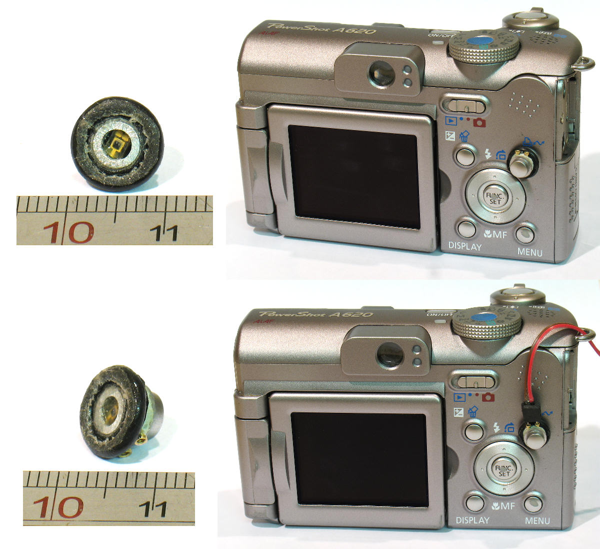
The above image shows one possible arrangement.
For testing, turn the LED on/off using the left/right buttons :-
@title LCD on_off
" Left-off, Right-on"
:loop
wait_click
is_key k "right"
if k=1 then blue_led_on
wait_click
is_key k "left"
if k=1 then blue_led_off
goto "loop"
end
Once your photo-detector electronics is working and you have tuned the pulse-width, send three bytes with 'send_data a, b, c' and use following code in Picaxe to display the three bytes as bit patterns :-
' -----------------------------------------------
' Display three bytes from camera as bit patterns
' -----------------------------------------------
SYMBOL DIODE_INPUT = 7
SYMBOL LED = 6
SYMBOL BIT_TIME = 3000 ' 30 msec divisor for 20 and 40 msec '0', '1' pulses.
pause 500
serout 7,N2400,(254,1)
pause 30
main:
do
PULSIN DIODE_INPUT,0,w6
loop while w6 = 0
gosub get_bytes
b1 = b0;
gosub get_bytes
b2 = b0;
gosub get_bytes
b3 = b0;
do
PULSIN DIODE_INPUT,0,w6
loop while w6 = 0
gosub get_bytes
b4 = b0;
gosub get_bytes
b5 = b0;
gosub get_bytes
b6 = b0;
' --------------------
' Display bit patterns
' --------------------
serout 7,N2400,(254,128)
b0 = b4;
serout 7,N2400,(#bit7,#bit6,#bit5,#bit4,#bit3,#bit2,#bit1 ,#bit0," ")
b0 = b5;
serout 7,N2400,(#bit7,#bit6,#bit5,#bit4)
serout 7,N2400,(254,192)
serout 7,N2400,(#bit3,#bit2,#bit1,#bit0," ")
b0 = b6;
serout 7,N2400,(#bit7,#bit6,#bit5,#bit4,#bit3,#bit2,#bit1 ,#bit0)
' --------------------
' Blink LED if data valid
' --------------------
if b1 = b4 AND b2 = b5 AND b3 = b6 then high LED
pause 500
low LED
endif
goto main
' ----------------------------------------
get_bytes:
PULSIN DIODE_INPUT, 0, w6
bit0 = w6 / BIT_TIME
PULSIN DIODE_INPUT, 0, w6
bit1 = w6 / BIT_TIME
PULSIN DIODE_INPUT, 0, w6
bit2 = w6 / BIT_TIME
PULSIN DIODE_INPUT, 0, w6
bit3 = w6 / BIT_TIME
PULSIN DIODE_INPUT, 0, w6
bit4 = w6 / BIT_TIME
PULSIN DIODE_INPUT, 0, w6
bit5 = w6 / BIT_TIME
PULSIN DIODE_INPUT, 0, w6
bit6 = w6 / BIT_TIME
PULSIN DIODE_INPUT, 0, w6
bit7 = w6 / BIT_TIME
return
' ----------------------------------------
You can see a robotic rig that could benefit from this feature at http://www.instructables.com/id/Camera-Panorama-robot-head-panograph/.