Continuous-shooting synchronised-flash PCB
Damir Vrancic, designer of the '3D Lanc Master' has devised a circuit that allows single-shot, delayed single-shot or continuous-mode shooting via the USB remote.
It will also trigger an external electronic flash at shutter speeds up to 1/1000sec.
Damir was also jointly-involved in the development and testing of the USB-remote method of precision synchronisation.
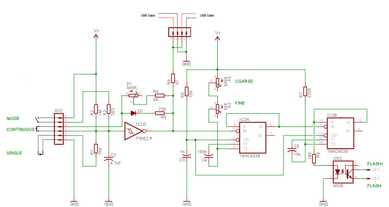
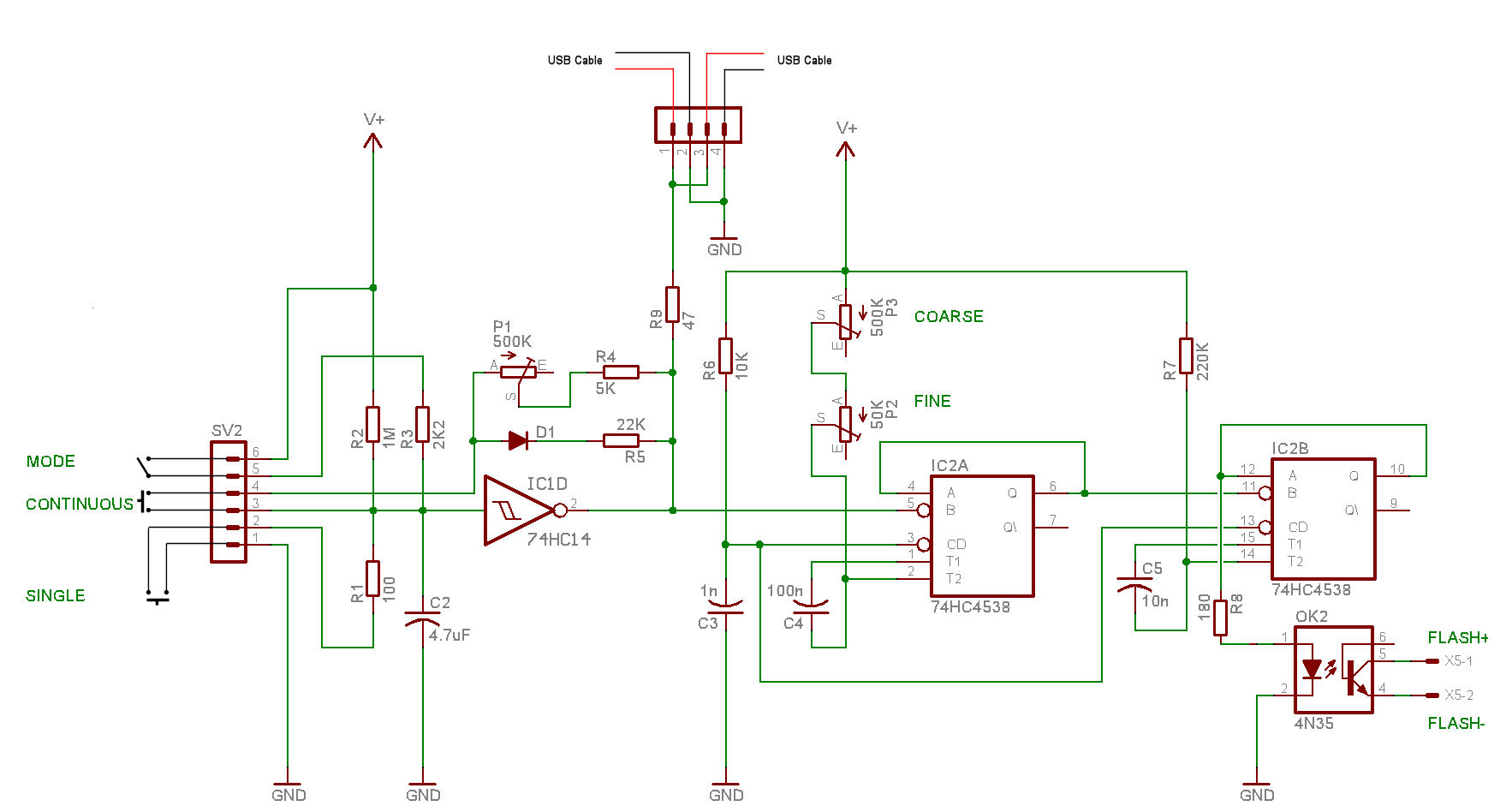
Click on the schematic for a larger version.
Power and Ground connections.
How it works
When the MODE switch is closed, capacitor C2 is charged to the battery voltage mainly via resistor R3 (R2 having little effect as it is far greater resistance).
The output of the inverting Schmidt trigger IC1D is low and so is the voltage on the USB +ve red wire.
Pressing the SINGLE shot button rapidly discharges C2 via R1 switching IC1D output high and applying the battery voltage to the USB connector.
On releasing the button, the capacitor quickly recharges via R2 and R3 and the voltage on the USB is returned to 0V.
If the MODE switch is open and you press the SINGLE shot button, on releasing it the picture will be taken after a delay of about five seconds (determined by R2/C2 time-constant).
When the MODE switch is open,capacitor C2 is initially charged by the high-value resistor R2 and IC1D output is low.
When the CONTINUOUS mode button is pressed, capacitor C2 is rapidly discharged via diode D1 and resistor R5.
The output of Schmidt trigger IC1D rapidly goes high applying the battery voltage to the USB connector.
At the same time, the output recharges capacitor C2 via R4 and high-value resistance P1 until it again switches state.
P1 therefore determines the shooting repetition-rate and is adjustable up to about 0.9 seconds.
IC2A, capacitor C4 and pots P2 and P3 form a monostable pulse-generator triggered by the output of IC1D and it determines the delay before triggering the flash and has a maximum value of about 38msec.
IC2B and associated components provide a 1.5 msec pulse that triggers the external flash via an opto-isolator.
DO NOT substitute for the 74HC4538 .. alternatives may not provide sufficient current-drive for the opto-isolator.
For the fastest shooting-rate, we need to set the cameras to continuous shooting-mode and use a special script.
The SDM shooting-sequence proceeds from preflash stage (if flash is on) to final shoot when 'the button is released'.
The script, however, must see a permanently pressed-down 'shoot' button.
The following script, supplied with the download, achieves that aim :-
@title Remote Burst 1
@param a Wait sleep (10ms)
@default a 10
a = 10*a
:loop
do
until is_key "remote"
press "shoot_half"
press "shoot_full"
:loop1
do
until not (is_key "remote")
sleep a
if (is_key "remote") then goto "loop1"
release "shoot_full"
release "shoot_half"
goto "loop"
The first image will not have as good a synch as the images that follow.
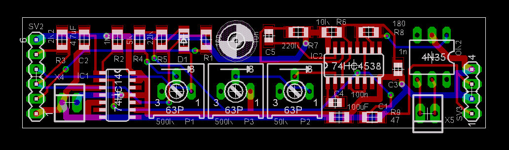
Component List
Eagle BRD file
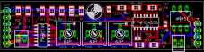
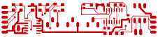
Top
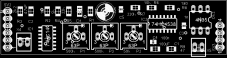
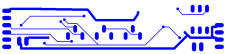
Bottom
The pcb's above are shown approximately life-size.
Click on the image for a 300 dpi version.
If you have any problems opening the files, download the free Windows (English) version of Eagle 5.0.0
The compact size of the boards allows them to be fitted inside a plastic or metal (with suitable insulation) tube and fitted with a rubber hand-grip.
It is just possible to fit on a 22x78mm board that will fit inside a Kaiser 'Angle Bracket - code 1100' and meet Olimex's 10-mil design rules.
The One or two 3V lithium batteries (or 6V silver-oxide) may be fitted on a circular base fitted inside the tube and about 10mm from the top.
It may be protected by a push-on plastic cap.
One or two series-diodes are recommended if using 6V.
Setting-up
Set the fine-adjustment pot P2 to the middle of its travel.
In a darkened room, set both cameras to 1/30sec in Tv mode, turn-off their flashes and run a remote-capture script with 'Synch Enable' enabled.
Do not enable 'Synch delay Enable' ... the delay is now provided by the electronics instead.
With the external flash turned-on and coarse-pot P3 at its high-resistance end, take a series of images.
Gradually reduce the value of the coarse pot between shots until the flash does not illuminate the images.
Gradually increase the fine-pot until both images are illuminated.
You can then increase the shutter-speed and, if necessary, adjust P2.
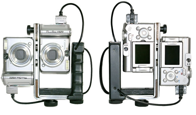
A possible rig for the SDM-synched cameras is shown above (courtesy of Steve Boddy).
Unlike commercial products, no hard-wiring is required and there is no vulnerable external equipment.
Indication of synchronisation is not required because the cameras are always synchronised and synch does not drift with time.